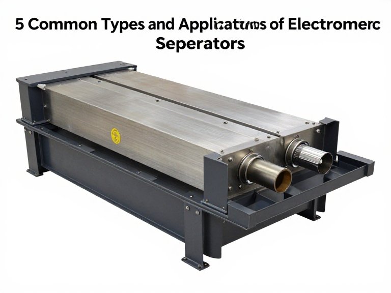
5 Common Types and Applications of Electromagnetic Separators
Quick Answer: Core Types and Applications of Electromagnetic Separators
The 5 common types and applications electromagnetic separator machinery addresses are: (1) Overband / Suspended Cross-Belt Electromagnetic Separators, deployed for coarse tramp iron extraction (bolts, rebar, bucket teeth) to protect crushers and shredders in mining, coal, and slag recycling; (2) Wet High-Intensity Magnetic Separators (WHIMS), utilizing matrix carousels (0.8 to 1.8 Tesla) for wet beneficiation of weakly paramagnetic hematite, limonite, and quartz/feldspar slurry purification; (3) Dry High-Intensity Electromagnetic Roller/Belt Separators, engineered for free-flowing mineral sands (zircon, rutile, ilmenite) and dry silica purification (0.5 to 2.0 Tesla); (4) High-Gradient Magnetic Separators (HGMS) / Water-Cooled Matrix Separators, delivering massive field gradients through expanded steel mesh for kaolin clay brightening and industrial wastewater treatment; and (5) Superconducting Magnetic Separators, utilizing cryogenic liquid-helium-cooled coils (3.0 to 5.0+ Tesla) to extract micro-fine, sub-micron iron staining from ultra-pure bauxite and electronic-grade quartz. For continuous bulk processing of coarse-to-medium dry feeds, industrial units like the Oromineral Dry Electromagnetic Separator provide the adjustable flux density and structural durability required to withstand abrasive operational environments.
Article Directory
- Magnetic Physics: Field Intensity vs. Field Gradient Explained
- Quick Summary Table: The 5 Electromagnetic Separator Types at a Glance
- In-Depth Teardown: 5 Common Types and Applications
- Featured Equipment Spotlight: Oromineral Dry Electromagnetic Separator
- Direct Technical Comparison: Mechanical & Electrical Performance
- Pros and Cons: Electromagnetic vs. Permanent Magnetic Systems
- Operational Realities: Thermal Decay, Cooling Systems, and Power Consumption
- Who Needs an Electromagnetic Separator vs. Who Can Use Permanent Magnets
- Costly Engineering Mistakes Operators Make in Magnetic Circuit Design
- Essential Sourcing Checklist: Auditing Industrial Magnet Manufacturers
- Expert Sourcing Verdict: The Metallurgical Circuit Blueprint
- Frequently Asked Questions
- Authoritative Mineral Processing Standards & Industry References
Magnetic Physics: Field Intensity vs. Field Gradient Explained
To evaluate the real-world applications electromagnetic separator equipment serves, you must look beyond raw manufacturer Gauss ratings. In our plant audits, we routinely see operators disappointed because a 10,000-Gauss magnet failed to pull fine hematite particles out of a flowing slurry stream. They assumed that high magnetic flux density alone dictates separation force. In particle mechanics, this assumption is physically false.
The magnetic tractive force ($F_m$) acting upon any mineral particle traveling through a separation zone is governed by the fundamental relationship:
$F_m = \mu_0 \cdot V \cdot \chi \cdot H \cdot \frac{dH}{dx}$
Where $\mu_0$ is the magnetic permeability of vacuum, $V$ is the volumetric mass of the particle, $\chi$ is the specific magnetic susceptibility of the mineral, $H$ is the magnetic field intensity, and $\frac{dH}{dx}$ is the magnetic field gradient (the rate of change of field intensity over distance). If a magnetic field is completely uniform—even if it measures an immense 2.0 Tesla—the field gradient is zero ($\frac{dH}{dx} = 0$), meaning the net translational magnetic force pulling that particle toward the pole is precisely zero. The particle simply aligns its internal dipoles and flows straight past the separator with the process stream.
For coarse tramp iron, where particle volume ($V$) is enormous and magnetic susceptibility ($\chi$) is high, a deep-reaching electromagnetic field with modest gradient is adequate. However, for weakly paramagnetic minerals—such as hematite, ilmenite, biotite mica, or wolframite—and fine particle sizes below 75 microns, particle volume shrinks to microscopic dimensions. To overcome the competing fluid drag force ($F_d$) and gravity ($F_g$), the separator must introduce physical flux concentrators (matrix elements like grooved stainless steel plates, steel wool, or diamond-mesh grids) that compress magnetic flux lines into razor-sharp spatial zones, producing gradients exceeding 10,000 to 50,000 Gauss/cm. Understanding how magnetic force competes against fluid drag is the central engineering principle behind our complete guide to the magnetic separator machine working principle.
Quick Summary Table: The 5 Electromagnetic Separator Types at a Glance
| Separator Type | Field Intensity Range | Process Medium | Feed Particle Size | Primary Industrial Target | Core Industrial Sector |
|---|---|---|---|---|---|
| 1. Suspended Overband | 0.1 – 0.35 T (Deep reach) | Dry Bulk Conveyor | Coarse (10 mm – 300+ mm) | Ferromagnetic tramp metal | Coal, aggregate, recycling, mining run-of-mine |
| 2. Wet High-Intensity (WHIMS) | 0.8 – 1.8 T (Matrix aided) | Liquid Slurry (20-40% solids) | Fine (0.02 mm – 2.0 mm) | Weakly magnetic iron ores, tantalite | Hematite beneficiation, quartz purification |
| 3. Dry High-Intensity Roller | 0.5 – 2.0 T (Adjustable) | Dry Free-Flowing Sand | Medium-Fine (0.074 mm – 5 mm) | Ilmenite, rutile, monazite, wolframite | Heavy mineral sands, glass sand, refractories |
| 4. Water-Cooled HGMS | 1.0 – 2.2 T (High gradient) | Viscous Slurry / Wastewater | Ultra-Fine (0.001 mm – 0.1 mm) | Iron-stained mica, titanium oxides | Kaolin clay bleaching, industrial effluent |
| 5. Superconducting Cryogenic | 3.0 – 5.0+ T (Liquid helium) | Fine Liquid Slurry | Sub-Micron (< 2 microns) | Lattice-bound iron, rare earths | Electronic-grade silica, bauxite upgrading |
In-Depth Teardown: 5 Common Types and Applications
1. Overband / Suspended Cross-Belt Electromagnetic Separators
In raw material processing, the suspended cross-belt electromagnetic separator is the primary defensive anchor of the entire crushing and grinding circuit. Mounted directly above high-speed conveyor belts carrying bulk run-of-mine ore, coal, or crushed aggregate, these units utilize large direct-current (DC) energized coils surrounding an annealed soft steel core to project a powerful magnetic field downward into the burden depth of the moving material.
The mechanical execution is built for severe industrial environments: a continuous, heavy-duty vulcanized rubber cleated belt wraps around the magnet body, driven by an explosion-proof motorized pulley. When a piece of ferromagnetic tramp metal—such as a broken roof bolt, loader bucket tooth, drill steel, or structural steel fragment—passes beneath the magnet, the magnetic field overcomes gravity and yanks the metal upward against the moving belt. The cleats sweep the metal out of the magnetic zone, discharging it into a collection chute. For heavy-duty secondary protection, operators frequently pair these units with a downstream 1.1kw Belt Magnetic Separator to catch smaller tramp shards before they reach sensitive pulverizers. Their dominant deployment spans coal-fired power utilities, iron ore load-out terminals, scrap metal shredding plants, and municipal solid waste recycling facilities.
2. Wet High-Intensity Magnetic Separators (WHIMS)
When target minerals are weakly paramagnetic and locked within fine slurry particle sizes, suspended air-core magnets are entirely useless. This is where the Wet High-Intensity Magnetic Separator (WHIMS) becomes indispensable. A WHIMS machine typically consists of a large, continuously rotating annular ring or carousel packed with grooved stainless steel matrix plates, rotating through a high-flux electromagnetic field generated by massive oil-cooled or water-cooled coils.
Slurry is introduced into the matrix cassettes while they are energized within the magnetic field zone (typically 0.8 to 1.5 Tesla). The grooved matrix concentrates the magnetic flux lines to razor-sharp peak gradients, capturing weakly magnetic particles like hematite, limonite, siderite, and wolframite onto the grooved teeth. Meanwhile, non-magnetic silica and quartz gangue wash freely through the matrix under gravity and hydrodynamic flow. As the carousel rotates out of the magnetic field zone, the magnetic field drops to zero, and high-pressure water spray manifolds flush the captured magnetic concentrates into collection launders. To examine fluid dynamics, pulsator stroke lengths, and matrix selections, study our technical analysis on the WHIMS magnetic separator working principle.
3. Dry High-Intensity Electromagnetic Separators
In arid regions where process water is scarce, or in industrial mineral circuits where drying slurry after separation is economically prohibitive, dry magnetic beneficiation is required. The Dry High-Intensity Electromagnetic Separator utilizes one or more high-speed induced-magnetic rollers or multi-disc assemblies positioned directly beneath vibratory feeding trays.
The dry feed—typically mineral sands, glass sand, or specialty chemicals sized between 74 microns and 5 millimeters—is fed in a uniform, single-particle-thick monolayer onto the separator belt. As the material enters the adjustable electromagnetic zone (0.5 to 2.0 Tesla), strongly magnetic minerals are pulled tightly against the belt and carried underneath the roller before being released into a concentrate bin. Paramagnetic minerals (such as ilmenite, garnet, and monazite) are deflected along intermediate trajectory arcs, while completely non-magnetic minerals (such as pure silica sand and zircon) follow natural ballistic trajectories off the nose of the roller. These separators are standard across the titanium feed supply chain, abrasive garnet manufacturing, and refractory mineral upgrading. For deep insight into process flowsheets, review our guide to the high intensity magnetic separation process.
4. Water-Cooled High-Gradient Magnetic Separators (HGMS)
High-Gradient Magnetic Separators represent the pinnacle of fine-particle purification for non-metallic industrial minerals. In applications like kaolin clay processing, raw clay slip contains sub-micron titanium oxide (anatase) and iron oxide impurities that impart an off-color yellow or brown tint, ruining the clay’s commercial brightness for high-grade paper coating and ceramics. Standard separators cannot capture particles beneath 10 microns because hydrodynamic drag in water easily overwhelms magnetic force.
An industrial HGMS utilizes a deep canister filled with fine, magnetized expanded metal matrix or compressed ferritic stainless steel wool. Surrounding the canister is a massive hollow-conductor electromagnetic coil cooled internally by continuous deionized water circulation. Operating at field strengths of 1.5 to 2.2 Tesla, the steel wool matrix generates localized field gradients exceeding 100,000 Gauss/cm. As the viscous clay slurry is pumped through the pressurized matrix canister, sub-micron iron and titanium specks are physically pinned against the matrix wires. Once the matrix becomes saturated with iron, the feed slurry is paused, the electromagnetic field is de-energized, and high-pressure backwash water flushes the matrix clean in a cyclic automated sequence. Sourcing an engineered Water-cooling Electro-Magnetic Separator for kaolin, feldspar, quartz is mandatory to achieve brightness ratings above 90% ISO.
5. Superconducting Cryogenic Magnetic Separators
When separation challenges exceed the physical limits of conventional copper-coil electromagnets, industrial processors turn to cryogenic Superconducting Magnetic Separators. Conventional copper coils reach an economic ceiling around 2.0 to 2.2 Tesla; pushing beyond that threshold requires enormous amounts of electrical power, generating massive Joule heat that melts coil insulation unless massive external chiller plants are installed.
Superconducting systems bypass electrical resistance entirely. Utilizing specialized niobium-titanium (NbTi) superconducting wire submerged in a closed-loop liquid helium cryostat maintained at -269°C (4.2 Kelvin), the electrical resistance drops to zero. A massive electric current can circulate continuously with negligible power consumption, generating colossal magnetic field intensities spanning 3.0 to 5.0+ Tesla across large processing bores. In our operational audits of kaolin and bauxite refineries, superconducting systems achieve extraction of lattice-bound iron and ultra-fine coloring bodies that no conventional separator can touch, while consuming up to 80% less electrical power than equivalent water-cooled copper installations. Discover the engineering schematics behind our JF Series Low-temperature Super-conducting Magnetic Separator with Liquid Helium for Kaolin & Bauxite.
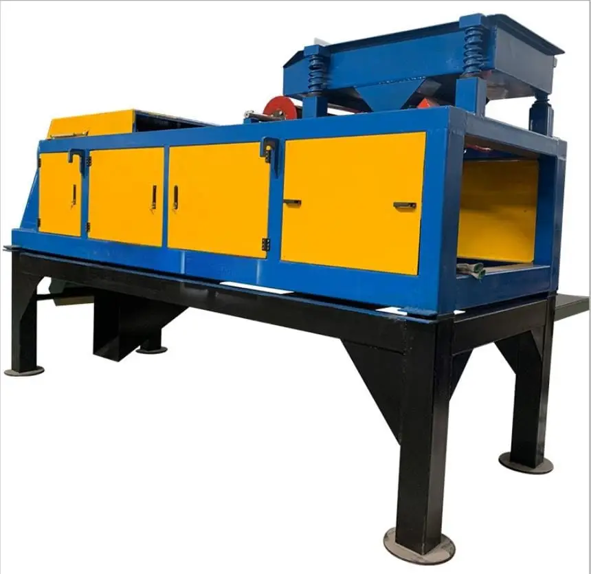
Featured Equipment Spotlight: Oromineral Dry Electromagnetic Separator
Engineered for high-tonnage continuous bulk processing, the Oromineral Dry Electromagnetic Separator bridges the gap between raw tramp iron defense and high-precision mineral sorting. Built with fully customizable frame metallurgy, adjustable flux density, and advanced thermal dissipation, it is the primary choice for modern dry processing lines.
| Equipment Type | Dry Electromagnetic Separator (Heavy-Duty Industrial) |
| Processing Capacity | 5 to 200 t/h (Calibrated to material bulk density and feed kinetics) |
| Max Feed Particle Size | ≤ 300 mm (Adjustable intake baffle based on circuit demands) |
| Magnetic Field Intensity | 0.5 to 2.0 Tesla (Dynamically adjustable via DC thyristor control) |
| Power Consumption | 15 to 300 kW (Engineered for optimal flux-per-watt efficiency) |
| Structural Metallurgy | High-tensile Stainless Steel, Cast Iron, and Abrasion-Resistant Alloys |
| Operating Temperature | Certified reliable continuous duty from -20°C to 50°C ambient |
| Overall Weight Envelope | 500 kg to 10,000 kg depending on target throughput and coil sizing |
Metallurgical Sourcing Advice: Eliminate unplanned crusher downtime and maximize dry ore recovery. Inspect complete engineering options on the official Dry electromagnetic separator portal, explore our full portfolio of Magnetic Separation Equipment, or consult our broader industrial survey on magnetic separation applications in industry.
Direct Technical Comparison: Mechanical & Electrical Performance
| Separator Architecture | Field Intensity (Tesla) | Field Gradient (∇B) | Electrical Power Draw | Cooling System Required | Maintenance Complexity |
|---|---|---|---|---|---|
| Overband Tramp Magnet | 0.1 – 0.35 T | Low (Deep reaching) | Medium (5 – 25 kW) | Air-cooled or natural oil convection | Low (Belt wear, motor bearings) |
| Carousel WHIMS | 0.8 – 1.8 T | Very High (Grooved plates) | High (30 – 150 kW) | External circulating oil-to-water | Medium-High (Matrix flushing, seal wear) |
| Dry High-Intensity Roller | 0.5 – 2.0 T | High (Induced roll teeth) | Medium-High (15 – 60 kW) | Forced air or closed transformer oil | Low-Medium (Thin belt tracking, roll wear) |
| Water-Cooled HGMS | 1.0 – 2.2 T | Extremely High (Steel wool) | High (50 – 250 kW) | Closed-loop deionized water chiller | High (Automated cycling valves, matrix plugging) |
| Superconducting HGMS | 3.0 – 5.0+ T | Maximum Achievable | Very Low Coil (10–25 kW Chiller) | Cryogenic closed-cycle Liquid Helium | Specialized (Cryostat vacuum, refrigeration) |
Pros and Cons: Electromagnetic vs. Permanent Magnetic Systems
| Technology Class | Commercial & Operational Strengths (Pros) | Inherent Operational Liabilities (Cons) |
|---|---|---|
| Electromagnetic Separators (Coil-Energized Field) |
|
|
| Permanent Magnetic Separators (Rare-Earth NdFeB / Ferrite) |
|
|
Operational Realities: Thermal Decay, Cooling Systems, and Power Consumption
Before issuing a commercial purchase order for heavy-duty separation equipment, plant engineers must confront the physical trade-offs of continuous electromagnetism. Sourcing an electromagnetic unit means purchasing a specialized thermal management system wrapped around an inductive electrical load.
The Reality of Thermal Decay (Cold vs. Hot Gauss)
One of the most common surprises for plant operators is the phenomenon of thermal decay. When you first energize a cold electromagnetic separator at the start of a shift, the copper coils operate at ambient temperature (e.g., 20°C). Electrical resistance is at its lowest, current flow is maximized, and the magnetic field reaches peak design strength. However, as direct current continuously flows through the conductor, Joule heating ($P = I^2R$) inevitably heats the coil. In standard Class H insulated coils, operating temperatures frequently climb to 100°C to 130°C within three hours.
Because copper has a positive temperature coefficient of resistance ($\alpha \approx 0.00393/\text{°C}$), the coil’s electrical resistance increases by approximately 40% when transitioning from cold ambient to hot operating equilibrium. If the DC power supply operates in constant-voltage mode, the current ($I = V/R$) drops proportionally. The consequence? A cold 3,000-Gauss magnet can lose 20% to 30% of its working magnetic field intensity once fully heated. If your plant relies on that marginal flux to extract weakly magnetic minerals, your tailings grade will spike mid-shift. High-performance units must incorporate automated constant-current thyristor rectifiers that dynamically raise voltage to hold excitation current steady, or deploy high-efficiency forced-cooling systems.
Selecting the Proper Cooling Medium
In most professional situations, the choice of coil cooling medium determines the long-term reliability of the separator:
- Air-Cooled (Natural or Forced Blower): Simple, dry, and lightweight. However, heat dissipation is poor, limiting these separators to low-to-medium field strengths or intermittent duty cycles.
- Oil-Cooled (Transformer Oil Convection): The excitation coils are hermetically sealed inside an expansion tank filled with high-dielectric transformer oil. Heat transfers from the windings into the oil and radiates through external cooling tubes. This is the industry workhorse for outdoor overland conveyors and harsh mining operations.
- Direct Water-Cooled (Internal Conductor Circulation): Deionized cooling water is pumped directly through the hollow interior core of square copper tubing while current flows through the metal wall. This provides the highest heat transfer efficiency known in conventional electromagnetics, enabling massive power inputs and sustained fields above 2.0 Tesla without thermal runaway.
Compare these cooling dynamics against passive alternatives like our Permanent Magnetic Separator or specialized Plate Type Permanent Magnetic Separation Equipment.
Who Needs an Electromagnetic Separator vs. Who Can Use Permanent Magnets
Every dollar in a mineral processing flowsheet must be justified through recovery yield and equipment uptime. Electromagnets provide decisive, high-ROI performance in demanding circuits, but they represent an unnecessary capital and energy expense in basic, low-burden sorting.
Operations That Must Invest in Electromagnetic Separators:
- Deep-Burden Run-of-Mine Overland Conveyors: When ore rides on 1,400mm to 2,000mm wide conveyor belts with burden depths exceeding 250mm, permanent magnets lack the physical flux reach to pull tramp rebar from the bottom of the rock layer. High-power suspended electromagnets project deep-penetrating flux fields that reach through the material to grab metal before it enters crushers.
- Variable-Grade Beneficiation Plants: If your plant processes complex polymetallic deposits where the feed grade shifts daily between high-iron hematite and low-grade tailings, having a variable DC control allows metallurgists to adjust the magnetic field on the fly to hit precise concentrate grade and recovery targets without re-tooling.
- High-Purity Non-Metallic Mineral Refiners: Producing quartz sand for photovoltaic glass or kaolin clay for paper manufacturing requires extracting weakly magnetic microscopic iron-titanium stains. These ultra-fine impurities require high-gradient matrix separators running between 1.5 and 5.0 Tesla—field levels that permanent magnets cannot physically achieve. For wet beneficiation flows, review our industrial Wet High Intensity Magnetic Separator systems.
Operations That Should Use Permanent Magnetic Separators:
- Shallow-Burden Recycled Aggregate Yards: If your facility crushes recycled concrete on narrow conveyor belts where burden depth never exceeds 75mm to 100mm, a high-grade Neodymium permanent cross-belt magnet provides exceptional ferrous extraction with zero power consumption and zero maintenance.
- Off-Grid and Remote Mobile Crushing Plants: Mobile crushing and screening contractors operating off diesel generator sets cannot afford to allocate 20 kW to 50 kW of generator capacity purely to energize an electromagnetic coil. Permanent magnetic head pulleys and cross-belts eliminate electrical load entirely.
Costly Engineering Mistakes Operators Make in Magnetic Circuit Design
Field Engineering Advisory: The “Burden Depth Velocity” Trap
The most pervasive mistake we witness on aggregate and mining sites is mounting an overband electromagnet perpendicular to a conveyor belt running at high line speed (exceeding 2.0 m/s). As burden depth increases and belt speed climbs, the dwell time a piece of tramp metal spends under the magnetic field window collapses to fractions of a second. At high velocities, the physical inertia of the moving rock holds the steel pin down faster than the magnetic pull can accelerate it out of the bed. For belts operating above 1.8 m/s, always orient the magnet in-line with the conveyor head pulley, capturing tramp metal as it is discharged in mid-air trajectory where gravitational resistance is momentarily neutralized.
- Failing to Account for Matrix Clogging in Wet HGMS Units: Operators frequently introduce slurry containing oversized coarse particles (>1.5mm) into fine-matrix magnetic canisters without adequate upstream vibratory screening. The coarse particles mechanically bridge across the steel matrix teeth, causing immediate slurry blinding, pump over-pressurization, and slurry blowout through overflow launders. Never operate a matrix-type separator without a certified protection screen upstream.
- Ignoring Transformer Oil Dielectric Degradation: In oil-cooled electromagnets operating in humid, dusty environments, moisture slowly enters via faulty breathers or cracked gaskets. Water contamination degrades the dielectric breakdown voltage of the transformer oil. When dielectric strength drops, internal coil arc-overs occur between winding layers, permanently burning out the magnet and requiring an expensive, full-coil rewind.
- Assuming Higher Belt Speed Always Increases Dry Roller Throughput: On dry high-intensity roll separators, operators often double the feed rate by speeding up the induced roller. As roller RPM increases, centrifugal force ($F_c = m \cdot r \cdot \omega^2$) grows exponentially. The centrifugal force throws weakly magnetic particles off the roller prematurely, preventing them from reporting to the magnetic concentrate bin and dumping valuable minerals directly into the tailings stream.
- Overlooking Electrical Control Interlocks: Installing an overband electromagnet without interlocking its power supply directly to the main conveyor drive motor. If the magnet trips its thermal overload breaker while the conveyor keeps running, hundreds of tons of unprotected ore will pass through, dumping tramp iron directly into the downstream cone crusher.
Essential Sourcing Checklist: Auditing Industrial Magnet Manufacturers
Before issuing a commercial tender or releasing funds for industrial magnetic equipment, require your prospective machinery manufacturer to provide documented proof of compliance across these four non-negotiable engineering benchmarks:
1. Verified Coil Construction Metallurgy & Insulation Class
Demand certified engineering drawings specifying winding materials. Settle for nothing less than:
- High-Conductivity Oxygen-Free Copper Winding: Avoid cheap aluminum-foil windings in heavy mining applications; copper provides superior electrical conductivity, higher thermal capacity, and far higher mechanical resistance to vibrational fatigue.
- Class H Insulation Standard: High-performance vacuum-pressure impregnated (VPI) Class H insulation rated to withstand continuous internal temperatures up to 180°C without dielectric breakdown.
- Dual-seal hermetic expansion tanks with desiccant silica-gel breathers and visual liquid-level sight gauges.
2. Certified Magnetic Flux Density & Gradient Mapping
Never accept a manufacturer’s brochure rating without an authenticated field-intensity test certificate:
- Demand an authenticated 3D Gauss/Tesla mapping chart displaying effective magnetic field strength measured at certified working distances (e.g., at 100mm, 200mm, 300mm, and 450mm from the magnet face).
- Verify that field measurements are conducted in accordance with international testing protocols governed by the IEEE Magnetics Society Standards and verified with calibrated Hall-effect Gaussmeters.
3. Regulatory Electrical & Mechanical Safety Compliance
Ensure that all rectifier enclosures, electrical junction boxes, and coil housings carry valid third-party certifications:
- Full operational compliance with the Society for Mining, Metallurgy & Exploration (SME) Technical Guidelines for Mineral Processing Machinery.
- Ingress protection rating of at least IP65 for junction boxes and power supply cabinets to protect electronics from high-pressure water washdowns and corrosive mining dust.
- Explosion-proof classification (ATEX, IECEx, or Class II Div 1) if the separator is deployed in combustible dust atmospheres such as coal handling or grain storage facilities.
4. Total Spare Parts & Global Manufacturing Provenance
A separator that sits idle waiting six months for custom replacement matrix plates or a proprietary rectifier thyristor destroys profitability. Ensure your manufacturer operates dedicated machining infrastructure, maintains readily available wear parts, and provides clear technical documentation. Benchmark global manufacturing standards by reviewing our analysis of magnetic separator manufacturers worldwide and leading magnetic separator manufacturers China.
Expert Sourcing Verdict: The Metallurgical Circuit Blueprint
In our professional assessment across decades of plant commissioning and mineral separation circuit design, continuing to rely on undersized or mismatched magnetic equipment is an expensive operational failure. Sourcing an electromagnetic separator is an investment that protects multi-million-dollar comminution assets and unlocks high-purity premium pricing for your mineral concentrates.
Here is your clear, actionable procurement roadmap for electromagnetic separation systems:
- For Primary Crusher and Conveyor Protection: Install a heavy-duty, oil-cooled Suspended Overband Electromagnet positioned in-line above the conveyor head pulley. Sizing must be calculated against maximum burden depth at peak surge tonnage to ensure deep tramp iron capture.
- For High-Tonnage Dry Minerals & Heavy Sands: Deploy the Oromineral Dry Electromagnetic Separator. Its adjustable 0.5 to 2.0 Tesla field intensity, robust structural alloys, and capacity up to 200 t/h allow plant metallurgists to dial in separation cut-points with precision while eliminating water consumption.
- For Fine Slurry Beneficiation (<1mm): Route your slurry through a Wet High-Intensity Magnetic Separator (WHIMS) or a water-cooled HGMS equipped with stainless steel matrix cassettes. Always install a self-cleaning safety trash screen upstream to prevent matrix fouling.
- For Sub-Micron Kaolin Brightening & Battery Quartz: Upgrade directly to Superconducting Cryogenic Magnetic Systems running at 3.0 to 5.0+ Tesla. The dramatic reduction in power consumption combined with unmatched sub-micron paramagnetic extraction delivers the lowest operating cost per ton of ultra-pure product.
To evaluate broader separation equipment architectures or configure custom machine dimensions for your plant flowsheet, review our foundational magnetic separation process guide and explore our full lineup of Magnetic Separator Machine systems today.
Frequently Asked Questions
The primary applications electromagnetic separator systems serve include tramp iron extraction ahead of secondary crushers, beneficiation of weakly magnetic ores like hematite and ilmenite, deep iron-stain purification of non-metallic minerals like high-purity quartz and kaolin clay, heavy mineral sands dry separation (rutile, zircon), and ferrous recovery from metallurgical slag and electronic waste.
Electromagnetic separators generate dynamic magnetic fields using direct-current energized copper or aluminum coils wrapped around soft iron cores, allowing operators to modulate field intensity (up to 2.0 Tesla in conventional units and over 5.0 Tesla in superconducting units) and cut power for instant self-cleaning. Permanent magnetic separators utilize static rare-earth neodymium-iron-boron (NdFeB) or ferrite blocks, providing a fixed field with zero electrical power draw but without the ability to turn off the magnet or vary flux density.
The magnetic tractive force acting on a particle is proportional to the product of magnetic field intensity (H) and the field gradient (grad H). A strong but uniform magnetic field exerts zero translational pull on a fine particle. High-gradient magnetic matrix systems introduce sharp steel grooved plates or expanded metal mesh that concentrate magnetic flux lines, generating localized gradients exceeding 10,000 to 20,000 Gauss per centimeter needed to capture micron-sized, weakly paramagnetic particles against slurry hydrodynamic drag.
Thermal decay occurs because copper and aluminum coil electrical resistance increases as temperature rises during continuous excitation (Joule heating). As coil resistance climbs, current draw drops at constant voltage, slashing magnetic field strength by 15% to 30% from a cold start. Industrial separators mitigate this through specialized cooling architectures: forced-oil circulation with external heat exchangers, direct water-cooling tubes embedded in hollow conductors, or transformer-oil natural convection.
Authoritative Mineral Processing Standards & Industry References
- Society for Mining, Metallurgy & Exploration (SME): Mineral Processing and Extractive Metallurgy Handbook – Magnetic Separation Circuits and Design Standards
- United States Geological Survey (USGS): Mineral Resources Program – Technical Reports on Industrial Mineral Beneficiation and Iron Contamination Remediation
- IEEE Transactions on Applied Superconductivity & Magnetics: Design Parameters, High-Gradient Magnetic Matrix Physics, and Coil Cooling Topologies